Program the robot in the assembly.
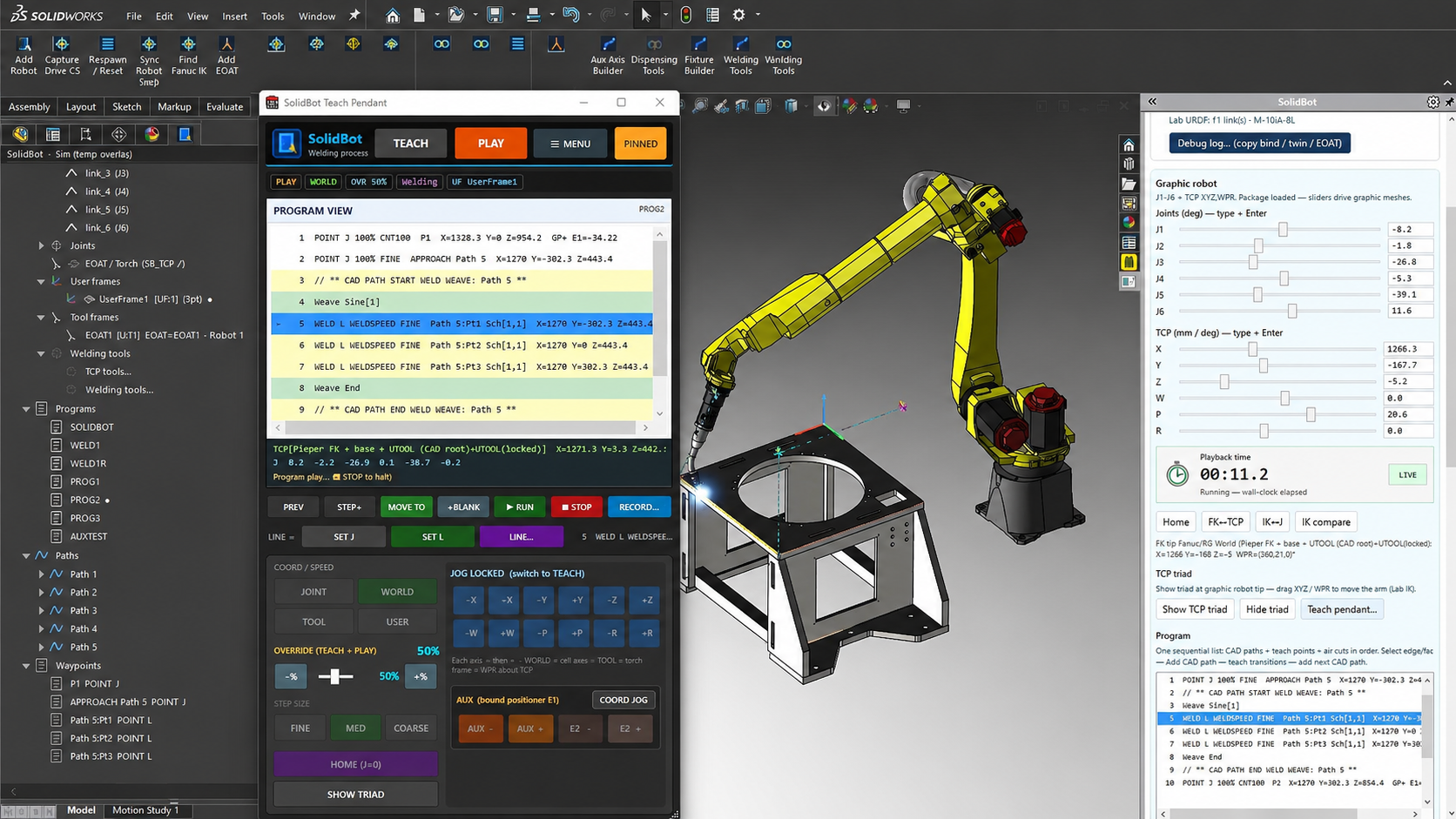
Create robot paths from live SOLIDWORKS geometry. SolidBot generates process paths, solves robot posture, and blocks export when configured reach, axis-limit, singularity, or interference checks fail—without rebuilding the cell in a separate OLP application. FANUC controllers are supported first, with more robot brands planned.
- SOLIDWORKS desktop add-in
- FANUC first; more robots planned
- 123 modeled FANUC robots
- Assembly-persistent paths
- FANUC LS output
Who it's for
Built for robot cells designed in SOLIDWORKS.
SolidBot is designed for automation engineers, robot programmers, integrators, and manufacturers who already use SOLIDWORKS as the source model for the cell—and do not want to rebuild that cell in a separate offline-programming environment.
- Robot system integrators
- Automation and manufacturing engineers
- Robotic welding and metal-fabrication teams
- Teams that design cells, fixtures, and parts in SOLIDWORKS
- High-mix or frequently changing production environments
What “SOLIDWORKS-native” means
SolidBot does not rely on generic “SOLIDWORKS integration.” It means specific workflow behavior:
- The user stays inside SOLIDWORKS.
- The cell is not exported into or synchronized with a second OLP application.
- Paths, frames, robot settings, and validation data are stored with the SOLIDWORKS assembly.
- Fixture and part revisions can be revalidated against the updated assembly.
- Controller output cannot be generated until the configured validation checks pass.
The workflow problem
Stop rebuilding the same cell in a second application.
Traditional OLP workflows introduce another model, another synchronization step, and another place for fixture or part revisions to drift. SolidBot keeps robot-path information connected to the SOLIDWORKS assembly where the cell was designed.
Traditional OLP workflow
- A second cell model, rebuilt or imported from the SOLIDWORKS design.
- A synchronization step every time fixtures or parts change.
- A separate place for revisions to drift out of alignment.
- Robot-path work disconnected from the assembly it was designed against.
With SolidBot
- One model: the SOLIDWORKS assembly you already designed.
- Paths, frames, and robot settings stored with that assembly.
- Revalidation against the updated assembly when revisions change.
- No export into a separate offline-programming environment.
Four-step workflow
From assembly geometry to robot program.
- 01Next step
Select process geometry
Pick the weld edges, faces, or features directly on the live SOLIDWORKS assembly. No separate cell model to rebuild or import.
- 02Next step
Generate the path and tool orientation
SolidBot generates the process path from the selected geometry and resolves torch/tool orientation along it.
- 03Next step
Solve and validate the robot motion
The robot posture is solved and the motion is checked against configured reach, joint-limit, singularity, and interference criteria on the modeled cell.
- 04Final step
Export controller-specific output
Once the configured checks pass, SolidBot produces controller-specific output — FANUC LS today, with more robot brands planned.
Differentiators
Why the assembly is the right place to program.
Assembly-native data
Paths, frames, and settings remain with the SOLIDWORKS assembly. There is no second model to keep in sync.
Predictable robot kinematics
Deterministic joint solutions with explicit robot-configuration handling, so the posture you validate is the posture you export.
For technical readers: inverse kinematics use a closed-form Pieper solution for spherical-wrist robot arms, with configuration branches handled explicitly rather than left to a solver.
Required validation gate
Configured validation failures prevent program export. Validation is a required gate, not an optional review step.
Controller-aware postprocessing
Controller-aware output for the explicitly supported controller families and applications — FANUC first, with more robot brands planned.
Product tour
A look inside the add-in.
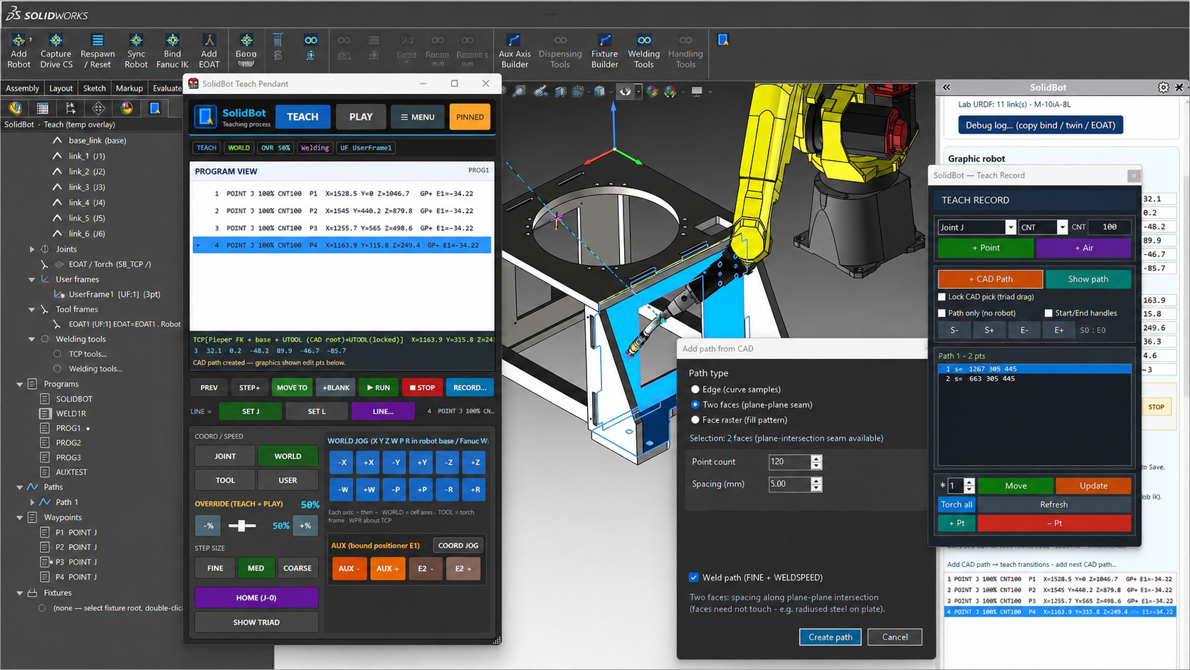
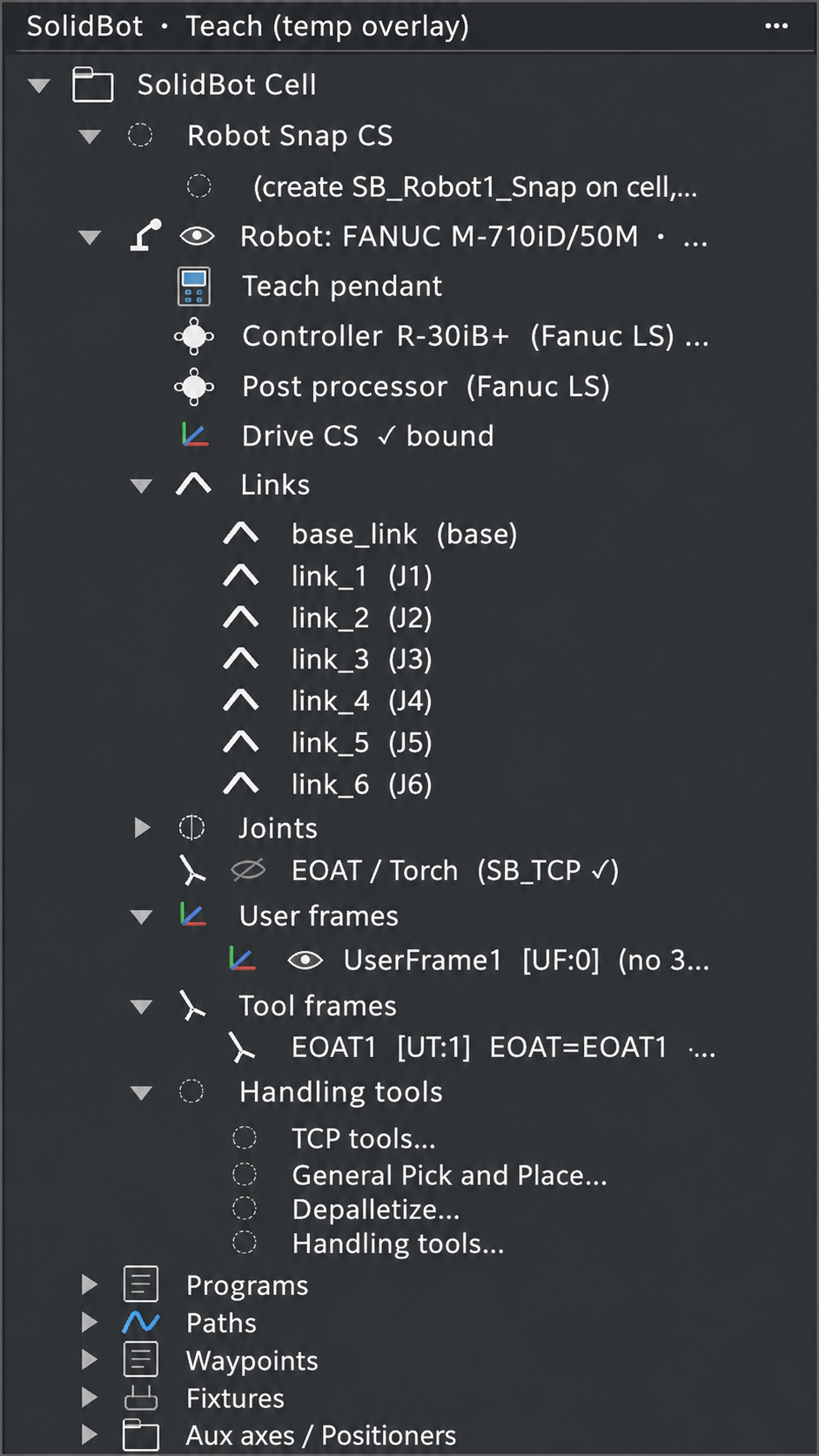
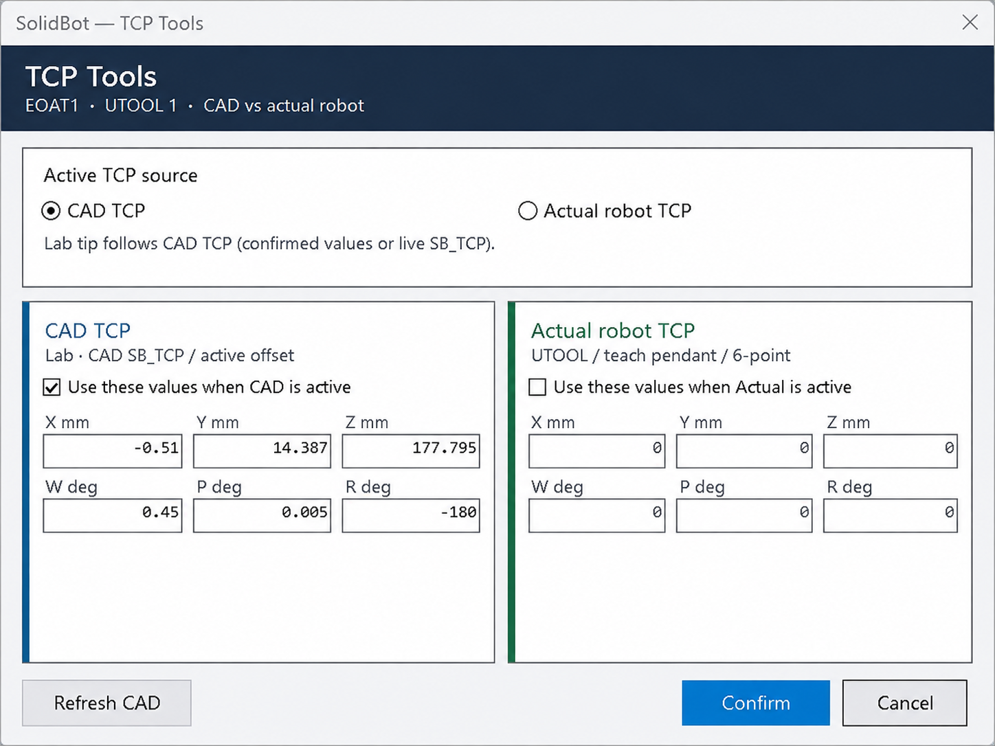
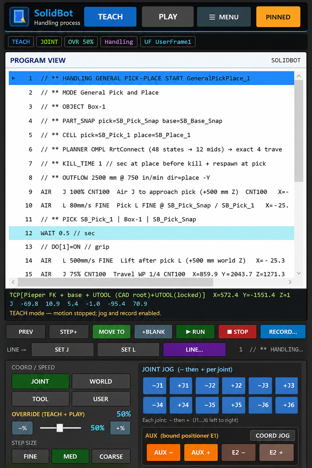
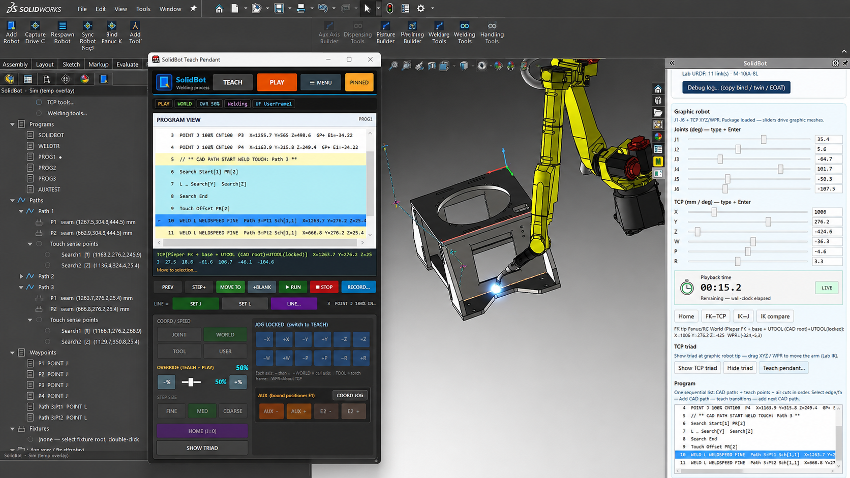
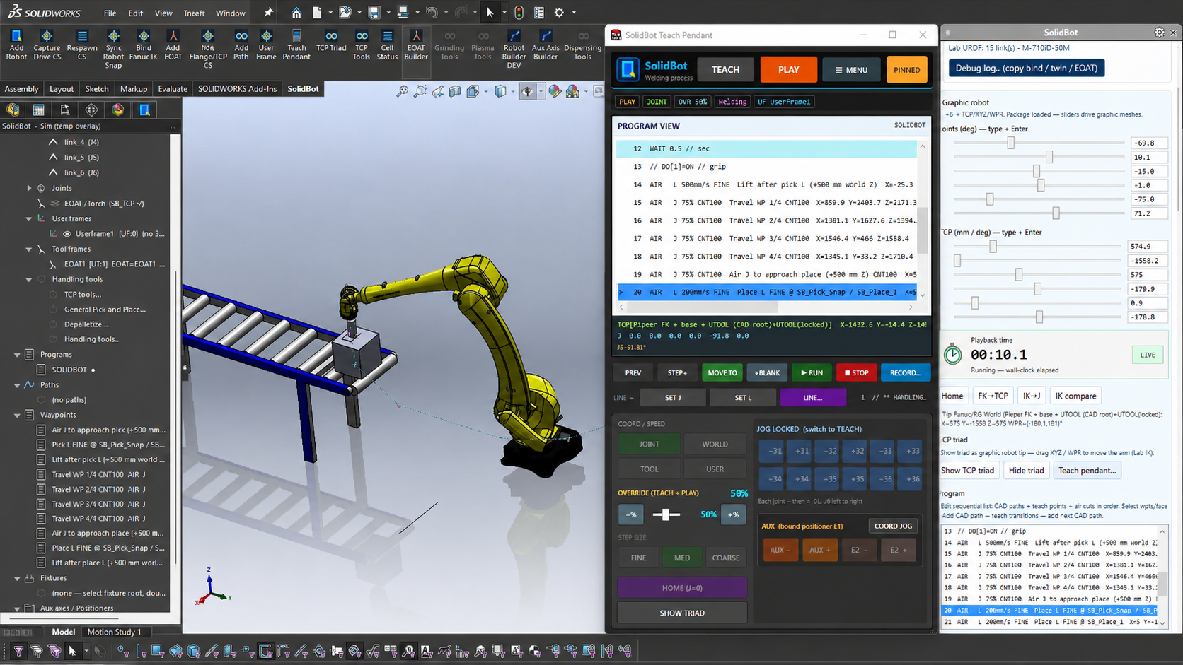
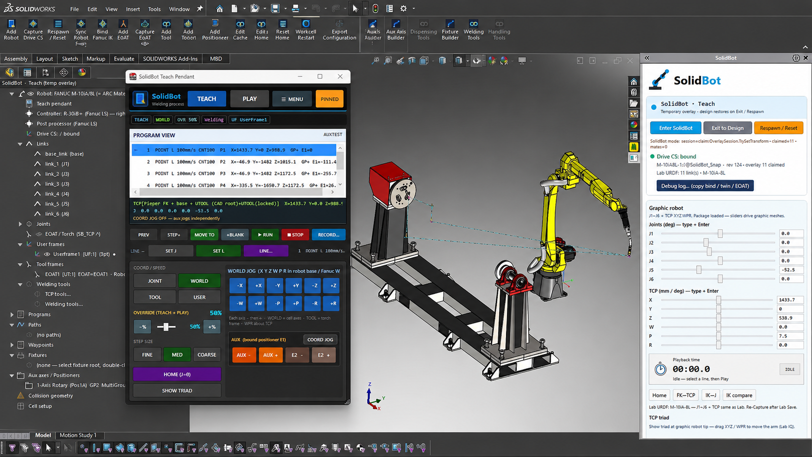
Cell builders, TCP calibration, the teach pendant, welding with touch sense and weave, and material handling — all running natively in SOLIDWORKS.
Technical validation
What the export gate actually checks.
SolidBot makes validation a required export gate rather than an optional review step. Programs that fail modeled reach, joint-limit, singularity, or interference checks are blocked from export.
Robot-model & joint-limit data
Each supported robot carries its kinematic model and per-axis motion limits, used as the basis for every reachability and posture calculation.
Inverse-kinematics method
Deterministic, closed-form inverse kinematics (Pieper solution for spherical-wrist robot arms) rather than iterative numerical solving.
Robot-configuration selection
Configuration branches (e.g. flip/no-flip, elbow up/down) can be selected and locked per path, so the exported posture matches the validated posture.
Reachability logic
Each target is tested for an in-limit solution within the robot envelope; unreachable targets are reported against the specific path point.
Joint-limit handling
Solutions that exceed configured axis limits are reported and prevented from passing the export gate.
Singularity detection & thresholds
Wrist, shoulder, and elbow singularity proximity is evaluated against configurable thresholds so near-singular motion can be caught before export.
Path sampling / interpolation
Generated poses are always evaluated, with interpolated samples taken between poses at a configurable resolution along each segment.
Controller-specific postprocessing
A controller-aware postprocessor emits FANUC LS output for the supported controller family from the validated motion.
Interference-checking scope
Interference checking uses SOLIDWORKS geometry from the modeled cell. Whatever you include in the assembly—robot links, torch or tool, fixture, workpiece, positioner, external axes, and surrounding cell equipment—participates in the check. Checks are evaluated at the generated poses and at interpolated samples between them, at the configured sampling resolution. SolidBot does not claim evaluation of the full continuous swept volume; discrete sampling can miss features smaller than the sampling step, so sampling resolution should be set appropriately for the cell.
Known assumptions & limitations
- Validation is only as accurate as the modeled cell; missing or simplified geometry is not evaluated.
- Discrete path sampling does not guarantee detection of interference between samples.
- Results reflect the digital model, not the calibrated physical cell.
- Supported robots, controllers, and applications are limited to those listed on the compatibility page.
Safety & commissioning
SolidBot validates against the configured digital model. Physical-cell calibration, controller verification, application-specific risk assessment, established robot safety procedures, and controlled low-speed commissioning remain required before production operation.
Software validation is not a substitute for physical safety certification.
Compatibility
Supported FANUC robots, controllers, and options.
SolidBot's architecture is robot-agnostic. FANUC is the first supported brand, with additional robot brands planned. The current modeled library covers 123 FANUC robots across the R-30iA, R-30iB, and R-30iB+ controllers. The rows below are a representative selection—confirm your exact model, controller, and options in a technical fit review.
- SOLIDWORKS
- SOLIDWORKS 2024+
- Windows
- Windows 11 (64-bit)
- Runtime
- .NET Framework 4.8
- Controllers
- R-30iA, R-30iB, R-30iB+
| Robot model | Family | Controllers | Application | Status | Required options | Ext. axis | Positioner | Coord. motion | Notes |
|---|---|---|---|---|---|---|---|---|---|
| ARC Mate 100iD | Arc welding | R-30iB, R-30iB+ | Welding | In development | ArcTool, ASCII Program Loader | Modeled | Modeled | — | Launch welding configuration. |
| ARC Mate 120iD | Arc welding | R-30iB, R-30iB+ | Welding | In development | ArcTool, ASCII Program Loader | Modeled | Modeled | — | Longer-reach welding arm. |
| ARC Mate 120iD/12L | Arc welding | R-30iB+ | Welding | In development | ArcTool, ASCII Program Loader | Modeled | Modeled | — | Extended reach variant. |
| M-10iD/12 | General / welding | R-30iA, R-30iB, R-30iB+ | Welding | In development | ArcTool, ASCII Program Loader | Modeled | — | — | Compact general-purpose arm. |
| M-20iD/25 | General / welding | R-30iB, R-30iB+ | Welding | In development | ArcTool, ASCII Program Loader | Modeled | Modeled | — | Higher-payload welding cell. |
| M-710iC/50 | General | R-30iA, R-30iB, R-30iB+ | Plasma cutting | Planned | TBD | Modeled | — | — | Roadmap application. |
| LR Mate 200iD/7L | Tabletop | R-30iB, R-30iB+ | Dispensing | Planned | TBD | — | — | — | Roadmap application. |
| M-10iD/16S | General | R-30iB+ | Pick-and-place | Planned | HandlingTool | — | — | — | Roadmap application. |
“Modeled” means the external axis or positioner configuration can be represented in the cell model. Coordinated positioner motion is planned and is not included in the initial welding release. Coordinated motion and multi-robot support are under evaluation. Direct LS loading requires the FANUC ASCII Program Loader / ASCII Upload controller option; see the FAQ for details.
Applications
Robotic welding first. More on the roadmap.
Robotic welding
In developmentLaunch applicationWelding is SolidBot's launch application. The list below is honest about what is in scope for the initial release versus what is planned. SolidBot does not claim to cover every function required to deploy a complete weld cell; exact scope for your configuration is confirmed during a technical fit review.
- Process path generation from geometryIn development
- Torch / tool orientation controlIn development
- Stitch / segmented pathsIn development
- Process I/O and weld instructionsIn development
- WeaveIn development
- Touch sensingIn development
- Seam trackingIn development
- Coordinated positionersIn development
- Multi-pass workflowsIn development
Plasma cutting
PlannedContour cutting paths from SOLIDWORKS geometry. On the roadmap after the welding launch.
Dispensing
PlannedBead and sealant paths with orientation control. Planned application.
Pick-and-place
PlannedHandlingTool-based material handling paths. Planned application.
Palletizing / depalletizing
PlannedStack build and teardown paths with configurable layers and part spacing. Planned application.
FAQ
Technical questions, answered directly.
Early-access waitlist
Join the SolidBot early-access waitlist.
Tell us which FANUC robot, controller, process, and SOLIDWORKS release you use. We'll use that information to evaluate technical fit, prioritize development, and identify candidates for early-access reviews.